

A bicontinuous microemulsion (BME, Winsor III), also called a middle-phase microemulsion, is a low-viscosity, isotropic, thermodynamically stable, spontaneously formed solution phase composed of water, organic solvent, and surfactants. The dynamic morphology of a microemulsion (ME) is generally determined by the hydrophilicity–lipophilicity balance (HLB) of the surfactants in the emulsion system, as shown in Figure1. When the hydrophilicity and lipophilicity of a surfactant are well balanced in an ME system, the ME frequently possesses a bicontinuous structure, in which the water phase and the oil phase coexist on a microscopic scale. In our laboratory, we are investigating polymer materials prepared from BMEs.1-5 Unique polymer morphologies such as continuous porous monolithic, bicontinuous hybrid, and nanosheet structures were prepared by polymerization or gelation in BMEs.
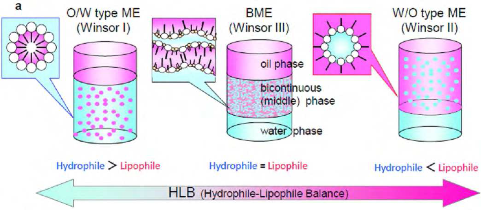 Figure1 Schematic representation and corresponding photographs of a series of MEs controlled by HLB (a, three types of ME model; b, functional ME (toluene/SDS + 1- butanol/saline). The phase structures of MEs were controlled by saline concentration.
Methods of forming monolithic bulk polymer products with continuous pores, based on spinodal decomposition processes, have been researched intensively; a major advantage of monolithic supports is that mass transfer can take place through their pores.Continuous porous polymer materials (molded monolithic porous polymers) can also be produced by decomposition of one component from a bicontinuous “gyroid” block-copolymer structure. Hashimoto and coworkers succeeded in obtaining continuous porous polystyrene (PS) with pores of diameter several tens of nanometers by dismantling polyisoprene by selective decomposition with ozone after having formed bicontinuous structures using PS/polyisoprene or polyisoprene/poly(2-vinylpyridine) block copolymers. Thermal polymerization of BMEs consisting of a monomer liquid (oil) and water with an initiator is the simplest way to immobilize a BME structure. Simple BME polymerization leads to formation of continuous porous structures based on a bicontinuous-solution structure. We conducted a similar thermal polymerization of styrene/SDS + 1-butanol/saline solution; the HLB was controlled by the cosurfactant and salt concentrations.1 A hard white cylinder with a porous structure was formed. A porous structure was clearly observed in scanning electron microscopy (SEM) images, as shown in Figure2. The observed network structure consisted of connected particles, indicating percolation. When the BME polymerization was conducted using a BME solution in which two electrodes were separately placed, the electroconductivity of the polymer product was similar to that before polymerization, indicating the presence of a continuous micro saline-phase. However, the obtained pore size was 10 times larger than that expected. Continuous increases in pore sizes and polymer-wall thicknesses are generally observed as BME polymerization progresses. This phenomenon is the result of phase separation induced by a shift in the HLB equilibrium during polymerization. This phase separation is essentially the same as spinodal decomposition from the liquid phase. The driving force of this phase separation is a decreasing affinity of the surfactant for the oil phase consisting of monomer and newly formed polymer. This was proved by the appearance of an oil/water phase when PS was added to a styrene BME solution. The nano/meso-structures of chemically immobilized BME polymers are therefore predominantly determined by competitive reactions between immobilization and meso-phase separation during polymerization. In other words, the pore size should be controlled by the polymerization speed.
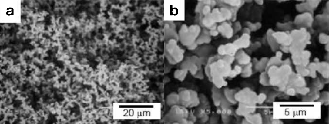 Figure2 Typical photographs (a, outer surface; b, torn surface) and SEM images (c and d) of the PS product prepared by BME thermal polymerization (styrene/SDS + 1-butanol/saline solution) in a glass tube.
BMEs are used to produce not only porous condensed polymer products but also a new class of unique soft gels. Soft materials (soft matter), which are easily deformed, are important in a wide range of technological applications. Stimuli-responsive (intelligent) gels, double-network (DN) gels, nanocomposite gels, and topological gels have been extensively researched in the past decade. Such gels are expected to have potential as polymer materials for actuators and drug-release systems; these are key polymer technologies of the future. We have conducted gelation in BMEs (toluene/SDS and cosurfactants/saline) to produce hydro-organogels.2 Organogelation and hydrogelation were respectively achieved by physical gelation with an organogelator and polymerization (chemical gelation) of acrylamide with a cross-linker. Then, three composite gel systems, namely a BME organogel, a BME hydrogel, and an organo/hydro hybrid BME gel, were produced by hydrogelation and/or organogelation of each solution phase.
Figure3 shows typical products obtained by gelation of macroscopic three-phase solutions including a BME phase. The BME phase (a middle-phase ME) is the middle phase of the macroscopic three-phase solutions. The upper and lower phases are a toluene phase and an aqueous phase, respectively. These gels, i.e., a BME organogel, BME hydrogel, and an organo/hydro hybrid BME gel, were self-supporting and very soft and elastic. Even in “one-side only” gelation products such as the BME organogel and the BME hydrogel, the solvent phases without a gelator were also macroscopically immobilized. No macroscopic pores were observed for any of the three BME gels. Moreover, all the BME gels had ionic conductivity, proving that the aqueous phase was continuous and that the bicontinuous structure was retained in the composite gels.
SEM images of freeze-dried one-side-gelated BME samples, i.e., the BME organogel and BME hydrogel, had uniform sponge-like porous structures, as shown in Figure3 (h-k). The walls of the porous structures consisted of fiber networks, which were essentially similar to those in bulk organogels or hydrogels. In contrast, the morphology of the both-sides-gelated BME organo/hydro hybrid gel was entirely different, with a pore-free and smooth surface (Figure3).
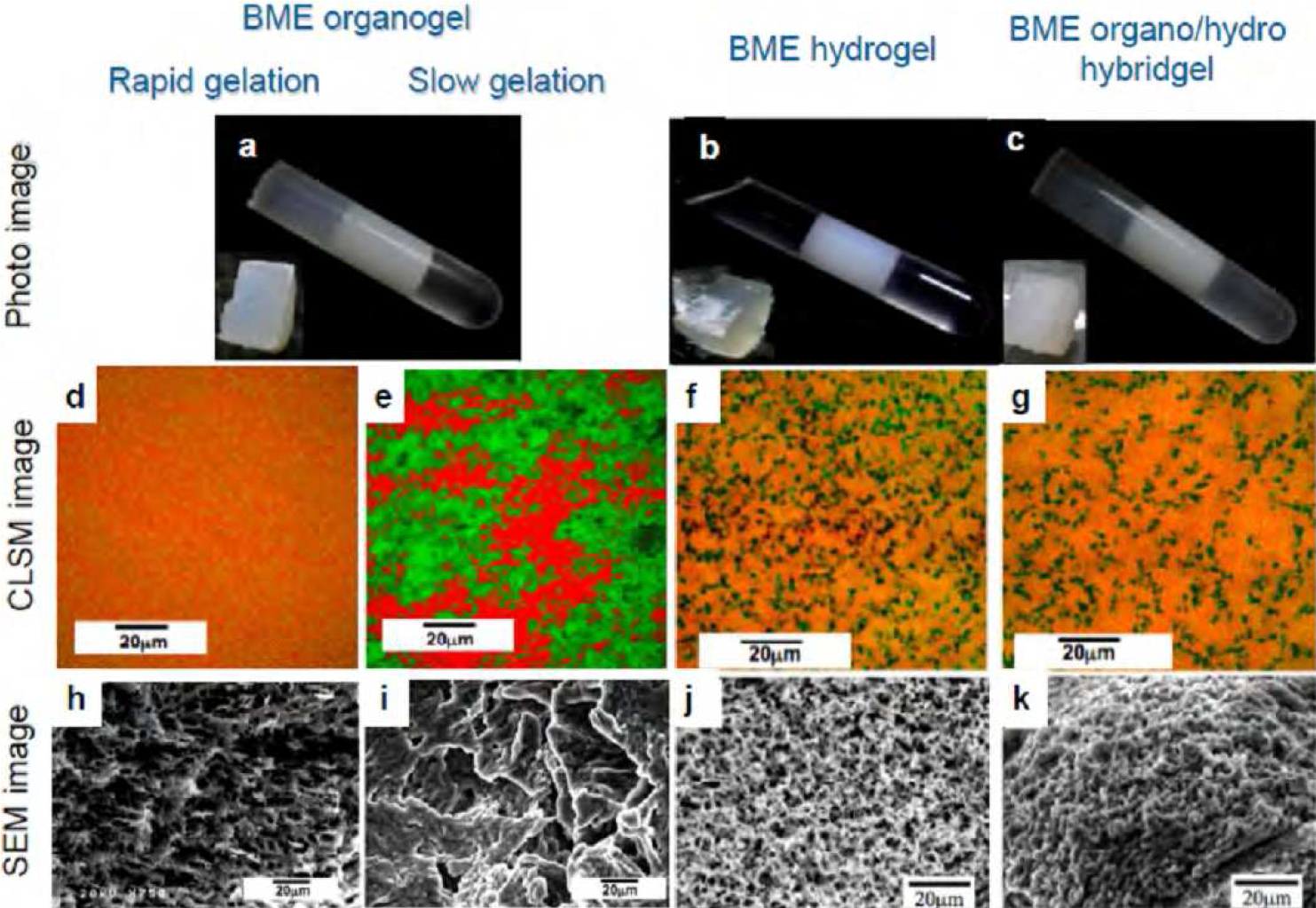 Figure3 Photographs (a–c), CLSM images (d–g), and SEM images (h – k) of a BME organogel (a, d, e, h, and i), BME hydrogel (b, f, and j), and BME organo/hydro hybrid gel (c, g, and k). The BME organogels were produced by “rapid” (d and h) and “slow” (e and i) cooling.
BME nanostructures are also attractive as media for electrochemical studies. The electrochemistry of redox molecules, namely K3Fe(CN)6 and ferrocene, in a BME (saline/SDS + butanol/toluene) was investigated in detail using various electrodes such as indium tin oxide (ITO), Au disk, GC disk, highly oriented pyrolytic graphite (HOPG), and alkanethiol-modified Au electrodes (Figure4).3-4 The electrochemical contact with the micro aqueous and organic solution phases in a BME is alternately or simultaneously achieved by controlling the hydrophilicity and lipophilicity of the electrode surfaces.The amphiphilic electrode (Au) revealed redox peak couples for both K3Fe(CN)6 and ferrocene in BME solutions simultaneously. In contrast, strong hydrophilic or lipophilic electrodes (ITO and HOPG) produced only one of the peak couples of K3Fe(CN)6 or ferrocene, depending on the affinities for the detecting electrodes. For instance, an ITO electrode possesses a strongly hydrophilic, negatively charged surface. No redox peaks resulting from ferrocene in a micro oil-phase were observed, although the redox peaks of K3Fe(CN)6 in a micro saline-phase were clearly observed. Conversely, strongly lipophilic (hydrophobic) electrodes such as HOPG, with a neutral surface, showed the opposite electrochemical response in the BME.The solution structure of a BME around the electrode changes thermodynamically in response to the HLB of the electrode surfaces. A well-balanced BME solution structure is easily converted to a biased or one-sided structure on an electrode surface to minimize surface energy. As mentioned already, the unique characteristics and structures of BMEs are based on the very delicate balance between the hydrophilicity and lipophilicity of the surfactant system; this balance is moderated by the concentrations of the cosurfactant and salt, or by the temperature.
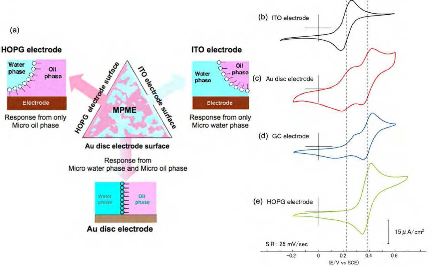 Figure4 Schematic representation of BME solution structures at solid/oil/saline interfaces (a) and typical cyclic voltammograms measured using ITO (b), polished Au disk (c), polished GC (d), and cleaved HOPG (e) electrodes in BME in the presence of K3Fe(CN)6 and ferrocene.
The formation of a polymer tube with continuous pores and seamless walls by simple polymerization in a capillary directed our attention to polymerization of BMEs in other microspaces, such as opal membranes, to construct hierarchical structures. When thermal polymerization of styrene- or MMA-based BMEs was conducted in the submicron gaps of a silica opal membrane, surprisingly various fractal surface structures consisting of vertical polymer nanosheets were obtained instead of the expected continuous porous PS-filled silica opal membrane.5 Simple styrene polymerization in the silica opal membrane gave a PS-filled silica opal membrane. Figure5 shows typical SEM images of the “turf-like” fractal surface of the opal membrane after polymerization of the styrene BME. Unique morphologies such as fractal surfaces consisting of closely spaced nanosheets and vertically extended nanosheets were grown from the gaps of a silica opal membrane. The surface densities and lengths of the nanosheets were roughly controllable by the polymerization conditions, specifically the thickness of the opal membrane and the amount of BME applied to the membrane. The closely spaced nanosheets were typically ca. 200 nm thick, 0.5−2 μm wide, and 1−4 µm in length. Very long nanosheet ribbons were formed by polymerization in a relatively thick opal membrane (typical thickness > 2 mm). The lengths of the longest nanosheets were several ten of microns; however, the thicknesses and widths were 100 nm and 0.5−4 µm, respectively, almost the same as for nanosheets prepared under different conditions. These results prove that a combination of a regularly ordered “solid” microspace such as an opal membrane and the dynamic solution/solution structure of the ME, which can change in response to a variety of circumstances, has the potential for construction of hierarchical polymer structures by self-organization.
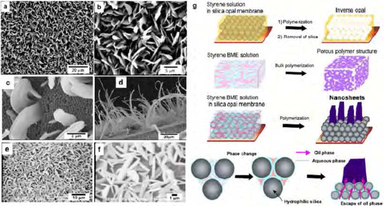 Figure5 Typical SEM images of PS (a–d) and PMMA (e and f) nanosheets prepared by polymerization of BME in silica gaps, and schematic representations (g) of the formation mechanism of nanosheets grown in the gaps of a silica opal membrane.
Figure6 summarizes the correlations among these three methods. The spinodal decomposition process is controlled kinetically, whereas micro-phase separation is completely thermodynamically controlled, with respect to the nature, shape, and length of each component.
The structures of polymer products near a contacting surface change considerably. In particular, a BME is a precise well-balanced system, which can be easily deformed by changes in conditions. In other words, BMEs can produce a great diversity of hierarchical nanostructures by self-organization. Moreover, a lyotropic LC phase is used as a template instead of the BME. A lyotropic LC phase can be intentionally prepared from a BME with a relatively high surfactant-concentration. Frequently, changes in the HLB during polymerization induces a phase transition to a lyotropic LC phase, giving ribbon, tape, and plate structures. It will be possible to use these methods to produce highly advanced, polymer materials with hierarchical nanostructures, in a way similar to that found in living systems.
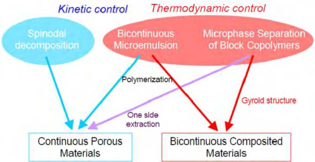 Figure6 Production of continuous porous materials and bicontinuous hybrid materials. The blue and red arrows (and areas) represent kinetically and thermodynamically controlled phenomena (or processes), respectively.
Copyright © 2008- KUNITAKE Laboratory.
